Basics Of Asphalt Mixing Plant Burner
- Atlas Technologies

- Oct 12, 2020
- 3 min read
The burner of an asphalt mixing plant determines its success. If you are well versed with the machine you will know how important the burner. The (Asphalt Plant) burner is the component which determines the success or failure of the product.
Any good quality burner of asphalt mixer will aim to use minimum fuel and generate maximum heat. This will enable to achieve maximum savings and give a faster return on investment.
Any type of asphalt plant be it continuous (drum type) or batch type machine comes with a burner for heating aggregates. If the aggregates are not heated properly, they cannot bind with bitumen and the end product will be bad. So, heating the aggregates evenly will help produce quality hot mix asphalt. Heated aggregates will play a major role in the success of hot mix asphalt. If the aggregates are hot, they will bind with bitumen.
Basics of Asphalt Mix Plant Burner – Batch Mixing Plant
Drying drum mixing plant is designed to work efficiently with the burner unit. It (Asphalt Mix Plant) will utilize the thermal efficiency of the burner and ensure that aggregates get maximum heat. Burner is a sealed-in combustion system that provides all the necessary combustion air. This ensures that the combustion air, plus 30% excess air, is available for efficient operation at maximum capacities.
The fuel-air ratio is maintained throughout the burner’s operating range with either mechanically or electronically linked valves. The burners will burn all commercial grades of fuel oil and natural gas, depending on the model and configuration of burner.
The burner provides a nominal 4: 1 turn down from its maximum firing rate. This provides efficient operation at various production rates. In most cases the available turn down is much higher.
Basic operation of hot mix plant burner:
The basic operation of hot mix plant burner steps are as below:
The basic model burner uses a firing rate control motor mounted to the combustion air damper which is mechanically linked to the fuel back pressure regulating valves [BPRV] and air damper.
The Programmable Logic Control (PLC) option to the burner control, adds additional sophistication to the management of the fuel/air ratio, by receiving the potential feedback form the control motor that manipulates the fuel valve or air damper position.
The PLC allows the fuel and air valve to be controlled independently as per the setting.
A combustion blower pressure switch (normally open) must be made to prove the blower is operating. This pressure switch is usually set at 15 Mbar.
The combustion air control damper must open to initiate the purge cycle prior to lighting the burner. a. The safety limit parameters must be satisfied. b. The purge pressure switch must be tripped for the purge cycle to begin. This pressure switch is usually set at 150 Mbar c. The plant flue gas exhaust fan must be confirmed to be running. d. The fan damper must be open enough for the calculated volume of air to flow during the required purge time. e. The minimum purge time is the time required for four volumes of air to flow through the heating chamber.
Before light-off the combustion air damper must be at the low-fire position.
The low-fire combustion air damper limit switch is set to close its contacts at the minimum fire light off position.
The low fire proof fuel valve limit switch (the switch that contacts the fuel valve linkage arm) must be closed with the low fire combustion air switch for the light-off sequence to begin
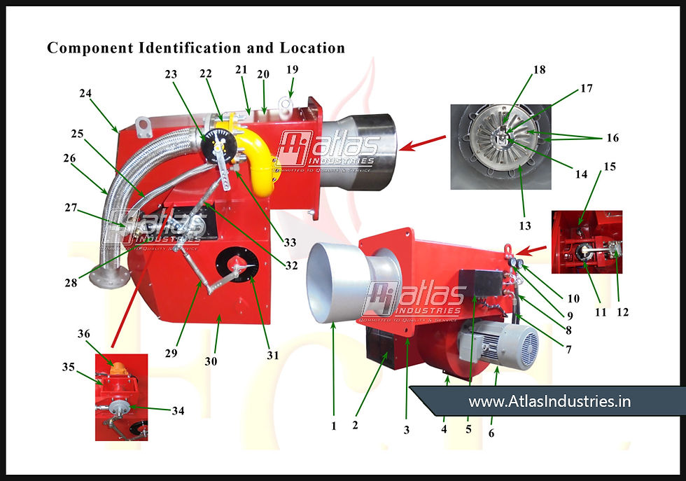
Components of asphalt mixing plant burner:
Below are the key components of asphalt mixing plant burner.

1.BLAST TUBE
2.DAMPER BLADES
3.MOUNTING FLANGE
4.LEG SUPPORT
5.JUNCTION BOX
6.BLOWER MOTOR
7.FUEL OIL RETURN PIPE
8.FUEL OIL INLET PIPE
9.RETURN PRESSURE GAUGE
10.INLET PRESSURE GAUGE
11.SOLENOID ASSEMBLY
12.BURNER ROD ASSEMBLY
13.DIFFUSER DISC
14.NOZZLE TIP
15.FLAME SENSOR / UV DETECTOR**
16.GAS NOZZLES**
17.IGNITION RODS
18.PILOT NOZZLES**
19.LIFTING HOOK
20.BURNER TOP PLATE
21.GUIDE BAR {NOT VISIBLE}
22.GAS CONTROL BUTTERFLY VALVE**
23.GAS FLOW INDICATOR**
24.BACK COVER
25.FLEXIBLE HOSE FOR PILOT BURNER**
26.FLEXIBLE HOSE FOR MAIN GAS SUPPLY**
27.BACK PRESSURE REGULATING VALVE {BPRV}
28.BPRV BRACKET
29.LINKAGE FOR AIR DAMPER
30.DAMPER BOX
31.AIR FLOW INDICATOR
32.LINKAGE FOR GAS**
33.AIR PRESSURE SWITCH**
34.ADJUSTABLE CAM DISC
35.MODULATING BLOCK
36.MODULATION MOTOR
**Parts that are incorporated with gas or malty fuel burners only.
Maintaining an asphalt plant will always be an important factor. In this the fuel consumption figures will play a major role. If the equipment is of good quality and a proper burner, it can do wonders for you. Contact us to learn about how we can help you with a good product fitted with an excellent burner unit.
More information Visit My Website>>https://www.atlastechnologiesindia.com/


Choose Rajasthan Lime & Minerals Pvt. Ltd., one of the most reputed hydrated lime manufacturers in Jodhpur, for reliable and efficient lime solutions tailored to your needs